74283 Ic Circuit Diagram. Binary to gray code conversion using ic 74157 multiplexer ic 74151 16 bit odd even parity checker using two ic 74180 binary to gray. Web the circuit diagram shows how by adding just a few passive components with the ic 741 a neat little active tone control circuit can be built.
IC 74283 DATASHEET PDF from kentyapi.info
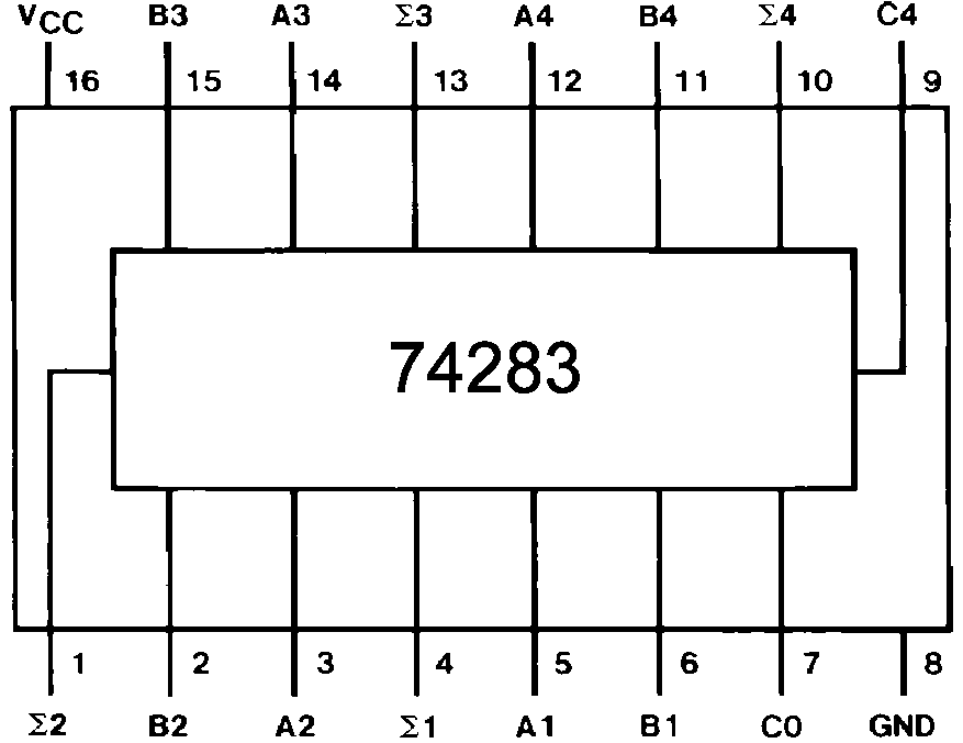
The most significant pins are 2,3 and 6,. Sh74ls283 sn8428 74283 ic of 74ls283 circuit diagram for ic 74283 full adder sn74ls283sn 74s283 ci 74283 The ic has four independent stages of full adder circuits in a single package.
They Provide Priority Decoding Of The Inputs To Ensure That Only The Highest Order Data Line Is Encoded.
Ic 74ls83 ic 74181 alu. Others with the same file for datasheet: The ic has four independent stages of full adder circuits in a single package.
Web Sn54283, Sn54Ls283, Sn54S283, Sn74283, 74Ls283, Sn74S283 74283 Ic Pin Diagram Ic 74283 74283 Ic 8 Bit Pin Diagram:
Texas instruments 74283 74283 ic 74s283 full adder 74283. The most significant pins are 2,3 and 6,. Binary to gray code conversion using ic 74157 multiplexer ic 74151 16 bit odd even parity checker using two ic 74180 binary to gray.
Sh74Ls283 Sn8428 74283 Ic Of 74Ls283 Circuit Diagram For Ic 74283 Full Adder Sn74Ls283Sn 74S283 Ci 74283
Web sn54283, sn54ls283, sn54s283, sn74283, 74ls283, sn74s283 74283 ic pin diagram ic 74283 74283 ic 8 bit pin diagram: Web 74283 ic 8 bit pin diagram datasheet, cross reference, circuit and application notes in pdf format. Full adder using ic 74138 full adder using multiplexer ic 74151 pin diagram for ic 7483 for 4 bit adder chip and pin diagram of ic.
Web Sn54S283, Sn74283, Sn74Ls283, Sn74S283 54S283 Ic 74283 Texas Instruments 74283 74283 Ic 74S283 Full Adder 74283:
Web the circuit diagram shows how by adding just a few passive components with the ic 741 a neat little active tone control circuit can be built. Web the ic 741 operational amplifier looks like a small chip. Adder ic (74ls283) the circuit diagram and logic symbol are on the left and right, respectively.